
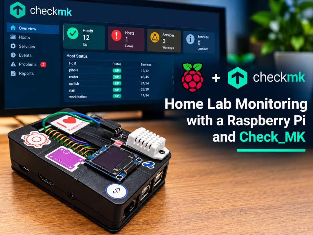
Home Lab Monitoring with a Raspberry Pi and Check_MK
Affiliate Disclosure: This post contains Amazon affiliate links. If you purchase a product through one of these links, I may earn a small commission at no additional cost to you. I only recommend products that I have personally used or believe are worth considering. My server rack doesn’t have a cooling solution like a data centre does. That isn’t practical in a home lab, but I still need to be conscious of temperature. Summers in England can bring scorching heat and winters can get very cold, and I want to be alerted when something is wrong before my servers crash. I also want to keep an eye on the power the rack uses, especially with electricity costing what it does now. I’ve used Check_MK to monitor my lab for years, and it’s already set up to email me alerts. So rather than build a separate system, this project feeds temperature, humidity and power readings from a Raspberry Pi into Check_MK, where I can set warning and critical thresholds like any other service. By the end you’ll have: Parts list The links in this list are Amazon affiliate links (see the disclosure at the top of the article). How it works Only two small services touch hardware: one reads the DHT22, one receives the radio messages from the power adapter. Each writes its latest reading to a tiny text file. Everything else, the display and the Check_MK agent plugin, just reads those files. That keeps the pieces independent, and it means two programs never fight over the same sensor. A few design decisions worth explaining: Building the unit The order of the build matters, because of how the Pi-mote fits. Fit the Pi-mote first The Pi-mote is a HAT: a board that plugs onto the Pi’s 40-pin GPIO header and sits over the top of it. I fitted it first. It covers pins 1 to 26 of the header, and every pin in the wiring table below (3.3V, GND, GPIO 4, SDA and SCL) is among them, so there was nowhere to push jumper leads onto those pins for the DHT22 or the display. Connecting the DHT22 and the display Because those pins are covered, I soldered the wires for the DHT22 and for the display straight onto the Pi-mote, at the pins that carry the connections we need. The pin numbers below are the usual ones for a Raspberry Pi 40-pin header. Check them against a pinout for your own board. The Pi-mote’s radio uses SPI and a few other pins of its own; in my build none of those clash with the connections below. Device Pin Header pin DHT22 VCC / + 3.3V (pin 1) DHT22 OUT / data GPIO 4 (pin 7) DHT22 GND / – GND (pin 9) OLED VDD 3.3V (pin 17) OLED GND GND (pin 14) OLED SDA GPIO 2 / SDA (pin 3) OLED SCK GPIO 3 / SCL (pin 5) Power the DHT22 from 3.3V, not 5V. With a 5V supply its data line can rise above what the Pi’s GPIO pins tolerate. A few practical tips for soldering onto a board that’s already fitted: Making room for the antenna The Pi-mote has a copper coil, its antenna, which sticks up from the board. A normal case lid would press down on it. So I cut a long rectangular opening in the lid with a Dremel rotary tool. The coil sits in the opening, and the lid closes properly without touching it. Take your time with this part. Mark the opening from the coil’s actual position and size, make the cut a little larger than the coil, and smooth the edges so they can’t catch the wires or the antenna. If you use a rotary tool as I did, clamp the lid down, wear eye protection, and use a cutting disc at a low speed, because plastic melts if the tool runs too fast. Finish the edges with a file or a sanding bit. Then close the lid and check nothing is pressing on the coil. The coil is how the unit hears the power adapter, so you don’t want it squashed or bent. Sensor placement: a lesson learned I first attached the DHT22 straight onto the Raspberry Pi case. It read about 25 °C while the room was 20 °C. The Pi itself was running at about 42 °C, and its heat was adding roughly 5 °C to the sensor’s reading, so my sensor was partly measuring the Pi, not the room. Humidity was affected as well. Relative humidity depends on temperature, so air that is warmed reads drier than it really is, which means a temperature error carries over into the humidity reading. Five degrees might not sound like much, but alert thresholds depend on it. With a warning level at 30 °C, an error of 5 °C uses up a large part of your margin. It isn’t a fixed offset you can simply subtract either, because the Pi’s temperature changes with how hard it’s working. So put the sensor on a cable and place it where it measures what matters, which is the air your servers breathe. That usually means the intake side of the rack at about mid-height. Avoid the exhaust, the top of a piece of equipment, and anywhere near a power supply or the Pi. The DHT22 uses a single data wire, so a few practical notes on the cable: If a longer cable causes read errors, the reader service logs a warning (shown later in the troubleshooting section) and Check_MK raises a stale-data alert. I moved the sensor off the case and onto its own extension cable, away from the unit. The only change to the build was the cable: no software changes were needed. Preparing the Pi With the hardware built, it’s time for the software. Install Raspberry Pi OS, then enable the interfaces we need. The OLED uses I2C and the Pi-mote’s radio uses SPI: Install the supporting packages and the libraries the scripts
Home Lab Monitoring with a Raspberry Pi and Check_MK Read More »